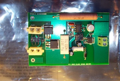
Power Integrating Module with Pulsed Driver
Power Integrating Module with Pulsed Driver
FEATURES
Two driver output interfaces, wire lead and terminal block
High current pulsed power output with less than 0.1% duty cycle
Less than 4Khz pulse frequency
- Less than 100ns pulse width
Can drive a wide range of light emitting devices
Two power input interfaces
Auxiliary power output
Automatic source switching
Input range from 6V to 15V
Robust input power transfer operation with fault tolerance
Versatile capabilities for power uses, driver uses, or both
ABSOLUTE MAXIMUM RATINGS
| Parameter | Type | Value | unit |
| PWR1, PWR2 |
Voltage Input |
20 |
Volts |
| PWR1, PWR2 |
Continuous Current Input |
15 |
Amps |
| OPERATING TEMPERATURE |
Ambient |
70 |
Celsius |
RECOMMENDED OPERATING CONDITIONS: PWR1 > PWR2
| Parameter | Type |
Value |
unit | ||
| Min | typical | max | |||
| PWR1, PWR2 | Voltage Input | 6 | 15 | 20 | Volts |
| PWR1, PWR2 | Current Input | 0 | 8 | 12 | Amps |
| OPERATING TEMPERATURE | Ambient without heat sink | 0 | 40 | 70 | Degrees Celsius |
| OPERATING TEMPERATURE | Ambient with heat sinks | 0 | 70 | 125 | Degrees Celsius |
| VOUT | Output Voltage | 6 | 15 | 20 | Volts |
| IOUT | Output Current | 8 | 12 | Amps | |
PULSED DRIVER DATA
| PARAMETER | TYPE |
VALUE |
UNIT | ||
| MIN | TYPICAL | MAX | |||
| INPUT VOLTAGE | REGULATED | 6 | 20 | Volts | |
| INPUT CURRENT | 0 | 1 | Amps | ||
| OUTPUT VOLTAGE | PFET Gated Voltage | 6 | 15 | 20 | Volts |
| OUTPUT CURRENT | PFET Gated Current | 12 | 15 | Amps | |
| FREQUENCY | 3.5 | 3.57 | 3.676 | Kilohertz | |
| PERIOD | 272 | 280 | 288 | Microseconds | |
| PULSE DURATION | Time On | 27.2 | 28.0 | 28.8 | Nanoseconds |
| DUTY CYCLE | Time On | 0.01 | Percent | ||
Note 1: The values given are simulated or measured results and there is a chance that the actual operation of a unit differs from the operation characterized here. We recommend that test and measurement be performed before using these devices in critical applications.
Note 2: The values provided in this data sheet are subject to change without notice.
APPLICATIONS
| Description | SKU # | Stock Quantity | Price |
|---|---|---|---|
| Device with 13.5V on 12V off switching of primary power | POWIM-PD 13.5-12 |
20 |
$150 |
| 12V on 10V off switching of primary power | POWIM-PD 12-10 | OUT OF STOCK | $150 |
| Equal voltage, current sharing with 100mv difference switching of primary power | POWIM-PD 100MV | OUT OF STOCK | $150 |
Or use our ordering form ORDER NOW!