AN001 Last Update June 30, 2014
Using the Power Integrating Module to Stagger Charge Storage Batteries
By Benjamin Bacon, Owner, Plane Space Design
Note: This application has not yet been tested and may deviate from theory in your actual applications. Test it before use. These plans are provided as is. Plane Space Design assumes no liability in its appropriateness for any application. Use this plan at your own risk.
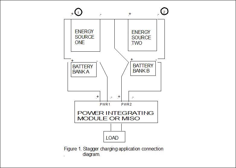 The Power Integrating Module (POWIM-) can be used to charge two sets of batteries alternately while they supply power to a load. The connection configuration
for this application is shown in Figure 1. The renewable energy sources are connected in series to the
Battery Bank A. Energy Source Two is connected to Battery Bank B only. The
battery banks are connected separately to the Power Integrating Module or
Dual-Input Single-Output Power Controller if a DISO is being used. The
Auxiliary Power output of the POWIM- (as opposed to the Pulsed Driver output) or
the output terminal of the DISO is connected to the load. When Battery Bank A is higher in voltage it will be passed through to the load by the
POWIM-. Battery
Bank B will be disconnected from the load and will be receiving charging current from the source. Thus
Battery Bank A will possibly be losing charge while Battery Bank B is
charging. When Battery Bank A falls below its switching threshold (12V) it will disconnect from the load and
Battery Bank B will now supply current to the load. Battery Bank A will start to charge from the source
(if it is available) while Battery Bank B drives the load until Battery Bank A charges to its cut on value (13.5V) at which point it
again replaces Battery Bank B as the power supply to the load. This cycle repeats continuously.
The Power Integrating Module (POWIM-) can be used to charge two sets of batteries alternately while they supply power to a load. The connection configuration
for this application is shown in Figure 1. The renewable energy sources are connected in series to the
Battery Bank A. Energy Source Two is connected to Battery Bank B only. The
battery banks are connected separately to the Power Integrating Module or
Dual-Input Single-Output Power Controller if a DISO is being used. The
Auxiliary Power output of the POWIM- (as opposed to the Pulsed Driver output) or
the output terminal of the DISO is connected to the load. When Battery Bank A is higher in voltage it will be passed through to the load by the
POWIM-. Battery
Bank B will be disconnected from the load and will be receiving charging current from the source. Thus
Battery Bank A will possibly be losing charge while Battery Bank B is
charging. When Battery Bank A falls below its switching threshold (12V) it will disconnect from the load and
Battery Bank B will now supply current to the load. Battery Bank A will start to charge from the source
(if it is available) while Battery Bank B drives the load until Battery Bank A charges to its cut on value (13.5V) at which point it
again replaces Battery Bank B as the power supply to the load. This cycle repeats continuously.
The Energy Source System
The energy sources are connected in series and their output voltages can be selected to aid in achieving the desired switching sequence. For the switching voltage levels we have selected, Energy Source Two should be a renewable energy source with an output of about 12 Volts. Now, Energy Source One does not have to be as large but can be about 3 V. Energy Source One will primarily be used to keep the voltage connected to PWR1 higher than the voltage connected to PWR2 and thus make PWR1 the main source to the load while renewable energy is available for battery charging and for driving the load. When the renewable energy fades Battery Bank A will still have a higher voltage and begin to discharge. If Bank A falls below 12 Volts, Bank B will be switched in and begin to drive the load.
The charging current to the individual banks is determined by the impedances of the batteries in the banks and the voltage across the banks. Battery Bank A will have a higher charging voltage across it (Energy Source One in series with Energy Source Two). This charging voltage will also have to drive the load and Battery Bank A may lose charge by having to drive the load too on occasion.
Most of the time, this will not be the case with Battery Bank B. It will have a lower charging voltage across it (Energy Source Two only) but since Battery Bank B is disconnected from the load when renewable energy is available or when Battery Bank A is fully charged, it does not lose charge to the load. This gives Battery Bank B an advantage for charging. Batteries that require more time to fully charge, like used batteries near replacement age, are ideally located in Battery Bank B.
The preceding circuit behavioral description assumes that both Energy Source One and Energy Source Two uses the same type of renewable energy. Different circuit behavior will result if the renewable energy sources are not the same type.
Adding Batteries to a Battery Bank
The utility of using a POWIM- to stagger charge batteries will be recognizable to most people who have used storage batteries in a renewable energy setting like solar power. In such a setting the situation exists that as you add more storage batteries to the system you have to add more solar panels to fully charge the batteries. The increase in the battery count necessitates more current to charge them to the same level in about the same amount of time. However, by stagger charging the batteries it will be possible to add more batteries and delay the need to add additional panels. The charging sources only needs to charge approximately half of the whole battery system at a time in a symmetrical pair of battery banks.
Charging Batteries of Different Ages
When a battery bank is composed of batteries of different ages, problems can arise from the older batteries charging to lower voltages than the newer ones and dragging the voltage of the entire bank down, and the older batteries create more heat and present higher impedance to the charging current. The Power Integrating Module is an ideal solution for this problem as it will allow the grouping of batteries into banks defined by age. The older batteries will be connected to the PWR2 input as this is the input that is recommended for use for backup or reserve power. PWR1 will connect to the newer batteries as this input is recommended for batteries that charge to the higher voltage. The voltage at the PWR1 input is controlled to remain above 12V. Below 12V PWR1 passes the output to PWR2 and PWR2 remains as the power source until PWR1 charges to 13.5V where PWR1 begins to drive the load again. In this way the newer batteries are allowed to operate at their peak performance level while the older batteries are relied on less and are kept from dragging the performance of the power system down. In the stagger charging configuration the older batteries have a better chance of charging to a useful voltage level too.