APPLICATION NOTE 008
Benjamin Bacon, Owner, Plane Space Design
One of the difficulties of working with 3-phase power in renewable power systems is encountered when the need to route the three power sources to one power storage system arises. This problem can be solved for wind generators if a Multiple Input Single Output (MISO) complex is constructed to switch the power to the energy storage system at the appropriate times. The operational functions of the MISO make it ideal for maximizing the efficient use of three phase generated power.
The behavior of a 3-phase power generator depends on how the three phases are connected. This can be Delta connection or Wye connection. Without going into the details of these connection methods it suffices to state the voltage and phase equations for the two types of connection.
For the delta connection the voltages are equal to the generator phase voltage and the phase differs by 120° per stage. In what follows below the generator windings are labeled A, B, and C and the sequence in which they are energized is positive or ABC.
VCA = Vp ∕0°
VAB = Vp ∕-120°
VBC = Vp ∕-240°
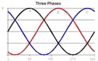
The following discussion also applies to the Wye connection of three-phase generators. In the equations the subscripts A, B, and C indicate the labels of the line voltages coming from the generator and the phase voltage that is between the two lines used together to form an output. Vp is the peak voltage of the generator. The diagram shows the phase relationship of the three voltages. They peak at points that are 120 degrees apart. Now this is the property of the three-phase generator that shall be used in the MISO to allow it to control the power in a useful way.
If the generator operates at a peak voltage of 14 V or less then the MISO can used to control the voltage outputs. MISO units can be daisy chained so that more than two inputs will be available. Two MISO units daisy chained will provide three inputs. Just enough for this three-phase generator.
The inputs of the MISO units are designed to control positive DC voltages primarily, but they can tolerate a negative voltage down to -14 V. The negative swing of the generator voltage can be tolerated to this level below ground without doing damage to the MISO. The part of the waveform that is of interest is at the top peaks but the negative swing has to be considered for safety's sake however.
The connections of two MISO units are to be made in the following way. Connect the Output of one MISO to the Second input of the other. The voltages VCA, VAB, and VBC are connected to the three remaining inputs. The remaining Output is the load output. Connect it to the energy storage system. When the generator is turned on the MISO complex will handle the voltages in a mixture of current sharing and and switching events.
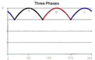
The only voltage and current that will be present at the load output will be from the one phase that is nearest its peak. The other phases will be blocked from the output. At the points where the waves cross the two voltages share the output for a very short time followed by switching the voltage that is going down off of the output.
Even though the waveform of the individual phases is truncated, there are still some benefits to the circuit performance. For one the highest portion of the voltage and the current is always on the load output. There is no time for which this is not true. Second the sinusoidal waveform is nearly rectified by the MISO and it can be converted to pure DC with a few additional components for conditioning the output.
The power switching at the input of the MISO will proceed in the above manner without loss up to a frequency of about 16 kHz. This is more than enough bandwidth for wind generators.